How to Build Rudder Blades & Centerboards - by J.R. Watson
When the centerboard of my Searunner trimaran broke in the middle of a windy race around the Black Hole, the question I kept asking was "why now, after working fine all of this time, and when we were leading the race?"
"Guess it just wore out" was my excuse to myself. This centerboard was built of laminated layers of plywood, resulting in a thickness of 2". It was then covered with two lavers of 6-oz woven fiberglass fabric. It was a deep and wide board with a lot of area, and like any rudder or centerboard on a boat that is sailed hard, it was exposed to a fair amount of stress.
The answer to "why now - while leading the race?" could have been fate. But there is a more scientific answer. Extensive laboratory testing at Gougeon Brothers, Inc. defines why the centerboard failed. Understanding why can help us design and construct components that will perform more efficiently and last much longer.
The plywood centerboard did, in fact, wear out - or more accurately - it failed from rolling shear fatigue. Fatigue cracks in a material result from repeated (cyclic) stress. Fatigue is a reality of all structures and materials, and eventually culminates in structural failure. Repeated loading and unloading or even worse, loading one way and then the ' other(reverse axial), rapidly reduces a material's physical integrity and accelerates degradation. The higher the load is as a percentage of the material's ultimate strength, the more rapid is the deterioration.
Materials
Some materials have a greater fatigue life than others. Ounce per ounce, wood is capable of operating at a much higher percentage of its ultimate stress level than most other materials. That is why such wonderfully efficient structures can be built with wood. However, plywood is not a good choice for cantilevered structures such as rudder blades and centerboards. This is because plywood is susceptible to rolling shear, shearing forces that roll the structural fibers across the grain.. Plywood's unidirectional wood fibers are laid in alternating layers, approximately half of them are oriented 90 degrees to the axis of the loads. Like a bundle of soda straws, which resist bending moments quite well one way, they simply lack cross-grain strength laterally and can roll against one another and fail under relatively low stress, especially in a cyclic environment. Therefore, when anticipated loads are primarily unidirectional, it is ideal to use a material with good unidirectional strength. Since only half of plywood's wood fiber is used to advantage, a plywood rudder blade or centerboard going from tack to tack (reverse axial loads) will fatigue much more rapidly than one built as described in this article.
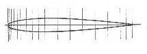
If you were to look at the end of the board, say a fish's view of a centerboard or rudder blade, you'd view its cross section. A section that has a faired airfoil shape is preferred over one that is flat with parallel sides. This is because the airfoil shape produces lift when moving through the water, thereby counteracting the sideward forces exerted by the sail rig. A flat section produces less lift and at a great expense of drag, slowing the boat and making it more difficult to steer.
Selection of a proper camber and section can be a subject of great theoretical debate. One can become intimidated with technical terms such as thickness distribution, Reynolds number, boundary layer, and so on. These terms do relate to the subject, however, for the builder/ sailor whose boat floats forlornly in need of rudder blade the following will do just fine. In fact, the best designers and builders will be hard-pressed to do better. An excellent choice for most craft, is a realistically accurate and fair NACA (National Advisory Committee for Aeronautics) 0012 airfoil, where maximum board thickness is 12% of the fore/aft length (chord length). Maximum thickness is located about 30% of the chord length measured from the leading edge (see sketch). The dimensions used to establish a specific shape (called offsets) are given in the appendix of The Theory of Wing Sections*. See the foil-owing article, How to loft Airfoil Sections. From offsets make a good drawing of half the section on transfer paper.
 Western red cedar and redwood are good choices of wood to use for rudder blades and centerboards for boats up to 25 feet. Both of these woods bond very well, are generally clear and straight grained, have good dimensional stability, are easily worked and affordable. Cedar is just a little heavier than the foams used for rudders, is much stiffer and has far greater shear strength values. On larger craft, a higher-density material like African mahogany is a better choice. Oak is not a good choice.
Construction
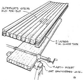
Buy flat-grained 2'x6s or 2'x8s, and then rip them to the designed board thickness. Turn every other ripping end-for-end to neutralize the effects of any grain that does not run exactly parallel to the blank, and to reduce tendencies to warp or twist (see sketch). Rotating the rippings 90 degrees to expose vertical grain will permit easier shaping with a plane. The last trick is to rip the end pieces of the nose and tail in half. Bonding with a couple of layers of glass tape between keeps the fine edge of the tail from splitting too easily and offers a precise centerline.
 Bond the ripping with a slurry of epoxy and 404 High-Density filler. Plastic strips prevent inadvertent bonding to leveled sawhorses (see sketch). With both sawhorses leveled, you're positive no twist exists in the laminated blank. Bar clamps should be snugged until excess glue squeezes from the joints. Over tightening only stresses joints and tends to squeeze all the adhesive from them. When the laminate is cured, a light planing to clean the surfaces is all that is needed before shaping begins.
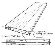
First, tack the 1/8"-thick plywood template that describes the cross section shape to the blank's ends. This is sawn from the impression made when traced with the transfer paper you originally drew it on. The key to producing an accurate and symmetrical board is maintaining of a systematic removal of material from one side, then from the other. To do this, mark the shape to be removed, stick to straight-line shapes (see sketch). Use a smoothing plane to remove the wood. After planing to the guide lines on one side, flip the blank over and plane the same shape on the other side. The procedure is similar to producing a round shape from a square by first forming an octagon, and then flattening the resulting eight comers to produce a 16-sided shape and refining that until very minute flat surfaces. Fifty-grit sandpaper bonded with 3M brand feathering disc adhesive to a 1/2"-thick by ll'x4.5"-wide plywood sanding block is a good tool to use for fairing this out.
Reinforcing the Blade
Now you should decide if the board needs reinforcement. Your board requires reinforcement if the chord thickness is at or below 4/o of the unsupported span. The unsupported span of a dagerboard or centerboard is that measurement from where it exits the hull, to its tip when fully lowered. The unsupported span of the rudder blade is that distance from the rudder case to the tip. If it is a non-retracting blade, measure from the waterline to the tip. So, if the board extends 48" below the bottom of the hull and is 2" thick, .04", it should be reinforced for strength and stiffness.
If the board needs reinforcement, graphite fibers are a good choice as the strain-to-failure values of wood and graphite fiber are quite similar, hence they enhance each others performance. The high-modulus qualities of the graphite fibers provide stiffness. The addition of graphite will efficiently increase stiffness and ultimate strength. Don't be intimidated by the high-tech qualities of graphite fibers, they are easy to work with.
The amount of reinforcement needed is usually figured at 101/o chord thickness. Using the same board for our example, the board is 2" thick, then 10% equals .20" total reinforcement,.10" per side. Graphite fiber tows are .01" thick, so 10 tows per side should give the necessary reinforcement to do the job.
The graphite fibers will be laid into a channel that is routed into the shaped board (see sketch). The specific depth of the channel is determined by the above rule. Make the channel a little deeper than what's required (1/16") so you won't be sanding the graphite fibers.
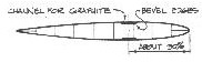 The profile of the channel is similar on all boards. The centerline of the channel is usually located at the point of maximum chord thickness (about 30% from the leading edge). The widest point of the channel is where the board exits the bull when completely lowered. The channel width at this point should be about 16% of chord length. Toward the ends of the board, the width of the channel narrows by about one third that of the widest dimensions Keeping this in mind, more graphite can be laid in that area, a little above and more below that point that exits the bull. Maintain a consistent channel depth throughout.
Take a one-inch-square stick to serve as a router guide. It's best to bevel the edge of the channel to reduce stress concentration. A rabbet plane serves best for this task. A layer of 6-oz fiberglass cloth is laid in the channel first (@ serves as an interface between the wood and graphite fiber), followed by the schedule of graphite. You can complete the entire bonding operation for a side in one session. Try to do the other side the next day. Finally, fair the reinforcement area with WEST SYSTEM brand epoxy and a low-density filler.
A layer of 6-oz woven-glass fabric should then be bonded to the faired board to improve the cross-grain strength and abrasion resistance. The radius of the leading edge should be about a 1% radius of the chord length, and may not permit the fiberglass fabric to lie flat around the radius. In that event, cut a strip of woven glass fabric on the bias (which will lie around a tighter radius) and bond it around the leading edge.
It is better to leave the trailing edge slightly squared rather than razor sharp. This will cause less drag and the centerboard will be less vulnerable to damage. Flatten the trailing edge to 1/16 or 1/8 of an inch on small boards, and closer to 1/4 of an inch on larger boards.
Axle Installation
Any board, no matter how stiff, will deflect. To prevent the axle hole that the centerboard pivots on from binding when deflection occurs, make the hole somewhat larger than the pin diameter. The perimeter of the axle hole should be thoroughly protected with fiberglass, as exposed end grain can absorb moisture.
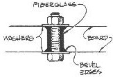 Abrasion of the axle against the axle hole dictates that you should bond fiberglass into hole's perimeter. To do that, wrap fiberglass tape around a waxed (use auto paste wax) metal rod that is about 10 to 15% larger in diameter than the actual axle pin. The hole should be heavily chamfered on each side, so when the wet layup is placed in the hole and the nuts tightened, the fiberglass is pressed by the large washers into the chamfers on both sides of the board (see sketch). The same procedure may be used on retractable rudder blades; but the tolerance between axle hole diameter and the diameter of the axle pin should be closer.
You can bond control lines for centerboards and rudders-in-place by wetting a slightly oversized hole (about 1.5" to 2" deep) with epoxy/404 @gh-Density filler mixture. It helps to mark the hole's depth on the rope with vinyl electricians tape to serve as a guide. Then, after soaking that end of the rope to be bonded in epoxy for a minute or so, shove it in the full depth of the hole.
Centerboards and rudder blades are often overlooked components that are of vital impedance to a boat's performance. Built correctly, they will reliably operate with the efficiency of a fish's fin, and you should note a measurable improvement in the quality of pointing and steering of your wind ship.
References
- Jozset Bodig, Ph.D., Benjamin A Jayne Ph.D., Mechanics of Wood and Wood Composites, Van Nostrand Reinhold Co., New York (1982)
- Johnston, Ken, Some 7houghts on Rudder Sections, Multihulls Magazine (Jan /Feb 1980)
- Eck Bransford, Everything You Ever Wanted To Know About 505 Fins.
- Lindsay, Mark, Centerboards and Rudders, Yacht Racing/Cruising Magazine (April 1981)
- Abbott and Doenhoff, Theory of Wing Sections, Dover Publications, Inc. New York (1959). How to Loft Airfoil Sections - by J.R. Watson
- Airfoils are cambered sections that are designed to produce lift (with minimum drag) as they operate in a fluid (air or water). Certain sections produce the most lift with the least amount of drag for a given condition.
When a designer chooses a foil section for a particular design, that section is often not produced to a close tolerance. I sailed on a boat that was noted for its erratic steering: the problem boiled down to an asymmetrical rudder. Operation of the airfoil section translates into measurable performance and handling benefits.
Whether you are going to build an airfoil from scratch or fair an existing foil with a template, you have to establish the section profile accurately.
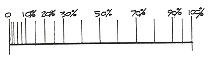
Airfoil sections of all NACA (National Advisory Committee for Aeronautics) families are obtained from dimensions off the centerline from specific station points. Station points begin at zero at the nose. The stations are spaced more closely in the forward third of the foil section's chord length. @ area carries more shape, thus requiring more reference points to define it.
Chord line is defined as the straight line connecting the leading and trailing edges (or centerline). Station locations are expressed as a percentage, measured from the forward #0 station, of the chord line. Chord thickness is described as a percentage of chord line, measured in half breadths at a particular station.
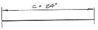
- Establish overall chord line length (c); our example is 24".
- Refer to NACA 0012 Basic Thickness Form. Calculate and mark the station locations (x)which are a percentage of the overall chord line length, measured from 0%.
- Calculate and mark the y dimensions (thickness from the chord line) at each station.
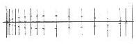
- Duplicate the y dimension points on the other half of the foil.
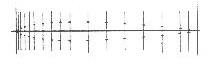
- Connect the plotted points with a batten or ship's curve.
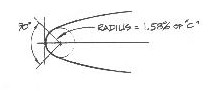
- Lay out the leading edge radius. The actual radius is a 90 degree segment of a circle drawn tangent to #O, bisected by the chord line. Its radius is 1.58% of the chord line length (c).
Durable Edges for Centerboards & Flip Up Rudders - by Jim Derck
When centerboards and flip up rudders drag across the bottom, the first fiberglass to abrade away is usually the leading edge at the bottom. This exposes the end grain of the wood, allowing water to be absorbed the length of the centerboard or rudder. The wood then expands, cracking the fiberglass along the leading edge and causing more problems. When it is time to repair the tip, it usually takes a long time to dry the wood for an effective repair.
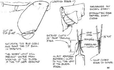
To isolate the end grain before applying the fiberglass, cut diagonally from the leading edge to the bottom, apply several coats of epoxy to both pieces and bond the tip back on. In the future, if the fiberglass cloth abrades away and the wood gets wet, it is quick to dry out the short length of end grain prior to making the repair.
Here is a technique for fiberglass covering that has proved over the years to provide a long lasting trailing edge. When rebuilding an existing blade or before applying fiberglass cloth to a new blade, plane a flat on the trailing edge about 1/8"-wide (wider for large rudders and centerboards). When applying the fiberglass cloth, position the rudder or centerboard horizontally so the leading edge is up. Drape the fiberglass over the foil and trim so that it extends 1/2" past the trailing edge. If you make a full-scale drawing of the trailing edge of your board or rudder, you will get a better idea of exactly how much fiberglass cloth to leave.
After the fabric is wet out, use an #807 syringe to apply epoxy thickened to a non-sag mix with 406 Colloidal Silica to fill the gap between the two layers of fiberglass cloth.
Squeegee out excess epoxy and align the trailing edge so that it is straight. If necessary, clamp a plastic covered straight edge in place to make the fabric conform to the shape of the trailing edge. After the epoxy cures, do the final shaping with a sander or sandpaper and a block of wood. Use caution, the edge can be very sharp!
Notes to the Chart
- The values listed beneath the NACA numbers are the distances + and - to the foil surface from the centerline in % of chord.
- Cut values for 0012 and 0018 in half to get 0006 and 0009. Double 0015 to get 0030. Halve 0006 to get 0003.
- It's conventional to make the chord 5% longer than you really want, and then slice off the last 5% to a blunt edge after laying out the foil profile. Example: you want a 20-inch chord rudder. Calculate profile based on 21 inches, leaving off last 5% or 1-inch when laying out.
- The nose of a NACA 00-- foil is always circular. Fair this in by eye as best you can using a compass or template or some sort (bottom of McDonald's coffee cup). This radius can be generated by the formula referred to above. (I'm still not talking.)
- The thickness of a NACA foil is always greatest at 30% of the chord from the nose.
| Distance From Nose | NACA 0012 | NACA 0015 | NACA 0018 | NACA 0021 | NACA 0025 | NACA 0030 |
| 1.25 | 1.89 | 2.37 | 2.84 | 3.31 | 3.95 | see note 2 |
| 2.50 | 2.62 | 3.27 | 3.92 | 4.58 | 5.45 | ---- |
| 5.00 | 3.56 | 4.44 | 5.33 | 6.22 | 7.41 | ---- |
| 7.50 | 4.20 | 5.25 | 6.30 | 7.35 | 8.75 | ---- |
| 10.00 | 4.68 | 5.85 | 7.02 | 8.20 | 9.76 | ---- |
| 15.00 | 5.34 | 6.68 | 8.02 | 9.35 | 11.14 | ---- |
| 20.00 | 5.74 | 7.17 | 8.61 | 10.04 | 11.95 | ---- |
| 30.00 | 6.00 | 7.50 | 9.00 | 10.50 | 12.50 | see note 5 |
| 40.00 | 5.80 | 7.25 | 8.70 | 10.16 | 12.09 | ---- |
| 50.00 | 5.29 | 6.62 | 7.94 | 9.26 | 11.03 | ---- |
| 60.00 | 4.56 | 5.70 | 6.84 | 7.99 | 9.51 | ---- |
| 70.00 | 3.66 | 4.58 | 5.50 | 6.41 | 7.63 | ---- |
| 80.00 | 2.62 | 3.28 | 3.94 | 4.59 | 5.46 | ---- |
| 90.00 | 1.45 | 1.81 | 2.17 | 2.53 | 3.02 | ---- |
| 95.00 | 0.81 | 1.01 | 1.21 | 1.41 | 1.68 | ---- |
| 100.00 | 0.13 | 0.16 | 0.19 | 0.22 | 0.26 | ---- |
| All Measurements in Percent of Chord | ||||||
This is not the last word on foils by any means but I hope to save YOU the time, energy and frustration involved in finding out The Real Foil Story Without Studying Fluid Dynamics Full Time.
Personally, I'd rather go sailing!